- July 22, 2024
- Posted by: MCAM Northwest
- Categories: Mastercam, Product Spotlight

Mastercam Tech Tip: Visual Linking for 2D and 3D Milling Toolpaths
We’re excited to bring you a tech tip showcasing one of the standout features in Mastercam 2025—Visual Linking for 2D and 3D Milling Toolpaths.
You may recall the introduction of visual linking enhancements in Mastercam 2024 for whole operations. This powerful feature has now been extended to cover the entire range of Milling toolpath groups, making it an even more indispensable tool for machinists and programmers.
What is the Visual Linking feature in Mastercam 2025?
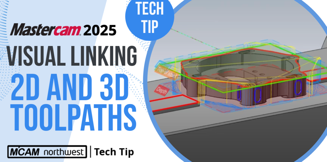
The Visual Linking feature in Mastercam 2025 provides a graphical representation of your linking parameters, allowing you to quickly and easily verify and adjust your toolpath settings. This enhancement simplifies the process of setting clearance, retract, feed, and top of stock planes, ensuring that your toolpaths are accurately defined and collision-free.
Visual Linking in Action
Let’s dive into an example using a part set up on a fourth-axis fixture. When we open the parameters for a Dynamic Mill toolpath and navigate to the linking section, we can see visual planes displayed on the screen. These planes correspond to the values set in the linking parameters, offering a clear, visual cue about where the tool will move.
For instance, adjusting the depth value in the linking parameters will immediately update the corresponding plane. This dynamic visualization helps prevent errors by providing instant feedback on the effects of your parameter changes. You can also interact directly with these planes—clicking and dragging them on the screen to set new values, and snapping them precisely where you need them.
Key Benefits of Visual Linking
One of the most significant advantages of this feature is its ability to highlight potential issues early in the programming stage. For example, in our fourth-axis part scenario, we might initially miss that our clearance plane is set below the part, inside the fixture. This oversight could lead to potential collisions. However, with Visual Linking enabled, the error becomes immediately apparent, allowing us to adjust the clearance plane above the part to ensure safe tool movement.
This feature isn’t just limited to 2D milling toolpaths; it extends to 3D milling as well. For example, in the steep/shallow section of 3D toolpaths, Visual Linking helps define where in the Z-axis space the toolpath will be applied. This is crucial when ensuring that toolpaths are correctly aligned with the part’s geometry, especially after repositioning the part in space.
Visual Linking in Lathe Operations
This new feature also shines in lathe operations. Whether you’re programming radial or axial toolpaths, the visual indication planes help ensure accurate toolpath definition. For instance, when setting up a dynamic peel mill operation, the planes can clarify whether the parameters are input in radial values or diametrically, reducing the risk of programming errors.
Visual Linking in Mastercam 2025 provides a powerful way to visualize and adjust toolpath parameters. By offering real-time feedback and interactive adjustment capabilities, it enhances programming efficiency and accuracy, helping you avoid costly mistakes and streamline your workflow.
For more information on Mastercam 2025 and how these new features can benefit your shop, please contact the MCAM Northwest sales team. We’re here to help you take your machining capabilities to the next level! Contact our sales team at (503) 653-5332 or email us at sales@mcamnw.com
Follow our Tech Tip series for more Mastercam tips and tricks.
Key Takeaways
- Enhanced Visualization: Mastercam 2025’s Visual Linking feature provides a graphical representation of toolpath linking parameters, making it easy to see and adjust settings like clearance and retract planes.
- Real-Time Feedback: Changes to linking parameters are instantly reflected in the visual planes, allowing for quick identification and correction of potential issues, reducing the risk of errors.
- Interactive Adjustments: Users can interact directly with visual planes by clicking and dragging them, simplifying the process of setting accurate toolpath parameters and ensuring proper alignment with part geometry.
- Increased Efficiency: By streamlining the programming process and providing immediate visual feedback, helping machinists save time, avoid costly mistakes, and enhance overall machining efficiency.
Follow MCAM Northwest!
LinkedIn: mcam-northwest
YouTube: The MCAM Northwest
Facebook: @MCAMNorthwest
X (formerly Twitter): @MCAM_NW
Come see us in person! Visit our Events page to see where we are headed next.